- Over speed trip
- L.O low pressure trip and alarm
- F.O low pressure alarm
- Jacket water high temperature alarm
- Jacket water high temperature trip
- Thermometer
- Pressure gauge
- L.O high temperature alarm
- Dip stick
- Crankcase relief valve
DAILY COLLECTION BOOK
What are the generator safety devices ?
Battery Charging On Board Ship
Batteries are one of the energy sources available on board vessels
which are used in case of blackout and emergency situations on board a
ship. These batteries apparently used for low voltage dc system like
bridge navigational instruments, emergency lighting, GMDSS, etc. and
thus kept charged to be used in case of emergency or need for temporary
power.
When the battery operation in a circuit is active, it provides current and voltage and is itself discharging. It will continue to supply the current to the equipment depending upon its capacity, which is measured in ampere-hours.
Hence, the arrangement is made available on board ship to charge the bank of batteries again after the use. Moreover, the arrangement should be such that the batteries can be fully charged on a timely basis as they gradually lose charge over a period.
The batteries can be charged with the help of dc power supply; however, presently there are no ships working on dc supply system and thus it is required to change the ac power into dc to charge the batteries.

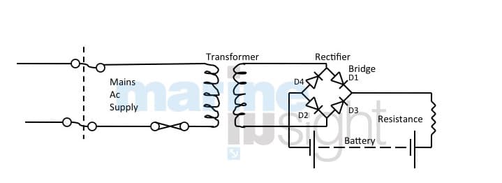
For converting AC into DC several components are required as shown in the circuit diagram above. First of all the AC is stepped down to the required voltage and then the AC is converted to DC with the help of rectifier system which changes sinusoidal wave of AC to DC system.
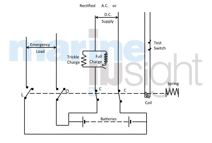
The only problem in the above circuit is that there is no arrangement provided for maintaining the charge, and the usage of the same circuit will lead to overcharging and reduction of the battery life. In order to avoid this, a slight modification is done on the same circuit and an arrangement is provided to maintain the charges at the terminals. Also, an arrangement to connect automatically to low voltage DC system is provided in case of a power failure.
In normal circumstances, the battery is charged using the full charge circuit and once the battery is fully charged, the charges on the battery are maintained by the trickle charge circuit.

As it can be seen in the diagram, the batteries are in standby mode with the charging switches C closed and the load switches L open. The positions of these switches are held with the help of an electromagnetic coil against the spring tension. The electromagnetic coil gets its supply from the main power source available on the ship. As soon as there is a loss of main power, the electromagnetic coil loses its power and the batteries are connected to load switch L which gets disconnected from the charging switch C.
Once the power is available from the main system, the batteries are connected back to the charging circuit again manually. Also, there is a test switch provided to test the system as a part of the routine tests.
To measure the condition of a battery, generally two parameters are taken, specific gravity and voltage. The specific gravity is measured using a hydrometer while the latter is measured using a voltage meter.
For additional safety purpose, in most of the modern ships, an interlock between the battery charger and the exhaust fan in battery charging room is installed. This is done to ensure the battery charging operation is interrupted when the exhaust fan is inoperative. This prevents a possible explosion due to hydrogen gas buildup caused by the battery charging process.
When the battery operation in a circuit is active, it provides current and voltage and is itself discharging. It will continue to supply the current to the equipment depending upon its capacity, which is measured in ampere-hours.
Hence, the arrangement is made available on board ship to charge the bank of batteries again after the use. Moreover, the arrangement should be such that the batteries can be fully charged on a timely basis as they gradually lose charge over a period.
The batteries can be charged with the help of dc power supply; however, presently there are no ships working on dc supply system and thus it is required to change the ac power into dc to charge the batteries.
A simple circuit used for battery charging is shown below

For converting AC into DC several components are required as shown in the circuit diagram above. First of all the AC is stepped down to the required voltage and then the AC is converted to DC with the help of rectifier system which changes sinusoidal wave of AC to DC system.
The only problem in the above circuit is that there is no arrangement provided for maintaining the charge, and the usage of the same circuit will lead to overcharging and reduction of the battery life. In order to avoid this, a slight modification is done on the same circuit and an arrangement is provided to maintain the charges at the terminals. Also, an arrangement to connect automatically to low voltage DC system is provided in case of a power failure.
In normal circumstances, the battery is charged using the full charge circuit and once the battery is fully charged, the charges on the battery are maintained by the trickle charge circuit.

As it can be seen in the diagram, the batteries are in standby mode with the charging switches C closed and the load switches L open. The positions of these switches are held with the help of an electromagnetic coil against the spring tension. The electromagnetic coil gets its supply from the main power source available on the ship. As soon as there is a loss of main power, the electromagnetic coil loses its power and the batteries are connected to load switch L which gets disconnected from the charging switch C.
Once the power is available from the main system, the batteries are connected back to the charging circuit again manually. Also, there is a test switch provided to test the system as a part of the routine tests.
To measure the condition of a battery, generally two parameters are taken, specific gravity and voltage. The specific gravity is measured using a hydrometer while the latter is measured using a voltage meter.
Hydrometer
The hydrometer is an arrangement made in which a float is placed in a cylindrical glass tube. The glass tube has a rubber bulb at one end and a rubber tube attached to the other. A scale is drawn on the glass tube, against which the level of the float is measured. To measure the charge, electrolyte from each cell is taken in the glass tube, and the specific gravity is measured. It is necessary that all the cells have almost the same charge. This specific gravity reading is related to the charge of the battery and must be corrected for the temperature of the electrolyte. For example, the approximate value of a fully charged lead-acid battery is 1.280 at 15 degree Celsius.Voltage
Apart from checking the specific gravity, the voltage is also monitored. Usually, the battery would show a voltage, which is slightly above its rated voltage. For e.g. a battery of 7 V should show nearly 7.7 V approx to indicate that it is fully charged. A value near to the actual rated value or slightly less (say 6.9 V) certainly indicates a discharged condition.For additional safety purpose, in most of the modern ships, an interlock between the battery charger and the exhaust fan in battery charging room is installed. This is done to ensure the battery charging operation is interrupted when the exhaust fan is inoperative. This prevents a possible explosion due to hydrogen gas buildup caused by the battery charging process.
Subscribe to:
Posts (Atom)